


In recent years, people have widely used fuzzy control technology in various fields of production and life. It does not rely on the precise mathematical model of the controlled object, has good adaptability, good system robustness and easy realization of no overshoot control [1] and is favored by the industry. Especially the two-dimensional fuzzy controller has attracted much attention because of its relatively simple design and high control accuracy. Based on the classic control method, this paper adds a proportional factor self-adjusting two-dimensional fuzzy controller to form a servo control system model. The S function of the M file is written to switch between the classic control method and the fuzzy controller. Simulation results It shows that the dynamic performance of the photoelectric tracking servo system has been greatly improved.
1. Mathematical model of photoelectric tracking servo system
The photoelectric tracking servo system is a dual closed-loop single-input single-output position follow-up system. The inner loop is a speed loop and the outer loop is a position loop. The control object for this article is the turntable of the photoelectric tracking system, and its transfer function is:
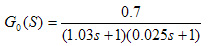
The speed loop and position loop controllers are designed using the lead-lag compensation method. The main components of the closed-loop system can be found in Reference [2], which will not be detailed here.
2. Fuzzy controller design
Control System Toolbox (Control System Toolbox) is a collection of functions and tools specifically designed for control system engineering in the MATLAB software package. The toolbox provides a wealth of algorithm programs to complete the design, analysis and modeling of general control systems.
SIMULINK is an interactive environment for modeling, analyzing and simulating various dynamic systems. With the rich function blocks provided by SIMULINK, dynamic system models can be quickly created. Fuzzy logic toolbox, using fuzzy logic-based system design tools, through GUI, can complete the whole process of fuzzy control inference system design, using simple fuzzy rules to model complex system behavior, and then apply these rules to fuzzy inference System; S-function is a powerful programming mechanism provided by SIMIULINK, through which users can implement their own algorithms.
1. The design and selection of fuzzy control input variables
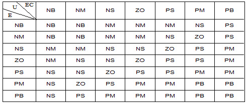
The fuzzy controller in the system adopts a dual-input single-output controller. The input variables are the deviation signal E and the deviation change rate EC. The output variable is the control quantity U. The quantitative domains of E, EC and U are all (-6 6), and the fuzzy subsets are all {NB, NM, NS, ZO, PS, PM, PB}. Type the FUZZY command in the command window of the MATLAB main interface to enter the FIS editor of the graphical user interface of the fuzzy controller, and establish the membership functions of E, EC, and U respectively. Here we choose the triangle (trimf) membership function.
2. Establishment of fuzzy control rules
There are two methods of fuzzy control rules: empirical induction method and inference synthesis method. The empirical induction method is used in this article.
The establishment of fuzzy control rules follows the following principles:
When the deviation is large in the positive direction and the deviation change is large in the positive direction, the output of the control quantity U should be in the positive direction;
When the deviation is small or zero in the positive direction and the error change is small or zero in the positive direction, the output of the control quantity U should be small or zero in the positive direction;
When the deviation is small in the negative direction and the error change is small, the output of the control quantity U should be small in the negative direction;
When the deviation is negative and the deviation change is negative, the output of the control quantity U should be negative;
Design fuzzy control rules in the FIS editor, as shown in Table 1:
Table 1 Fuzzy control rule table of photoelectric tracking servo system
3. Introduction to the simulation model of photoelectric tracking servo system with two-dimensional fuzzy controller:
As shown in Figure 1, the photoelectric tracking servo system is a double-loop follow-up system, which is composed of a speed loop and a position loop. On the position loop, the fuzzy controller and the conventional classic controller are designed to perform segmented control according to the system deviation.
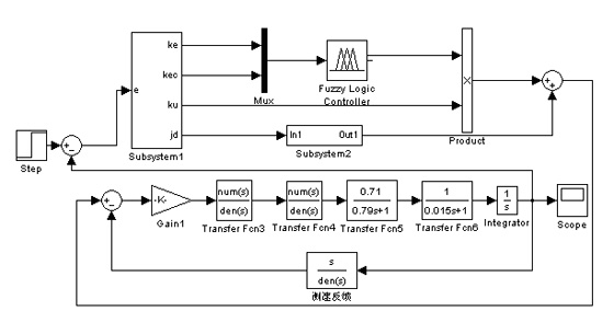
Figure 1 SIMULINK simulation model of photoelectric tracking servo system with self-adjusting factor two-dimensional fuzzy controllerFig.1 simulation model of SIMULINK of opto-electronic tracking servo system with self-tuning two-dimension fuzzy controller
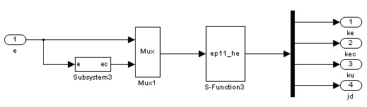
Figure 2 SIMIULINK simulation model of Subsystem
1Fig.2 simulation model of SIMULINK of Subsystem1
The Subsystem1 subsystem is shown in Figure 2. The deviations E and EC are the two inputs of the S-function. The output of the S-function is the scale factor Ke, Kec and Ku, and the input jd of the position loop conventional controller.
The S-function ep11_he.m can be used to switch between the two controllers, and the switch point is selected as 0.1. When the absolute value of the system deviation is greater than the switching point, the fuzzy controller works to reduce the system deviation rapidly; when it is less than the switching point, the jd port of Subsystem1 subsystem outputs e, and the conventional controller controls the work to ensure the system control accuracy [3 ]. ep11_he.m configures the scale factors Ke and Kec of the two inputs E and EC of the fuzzy controller. Because the value of the scale factor Ke and Kec has a great influence on the dynamic performance of the photoelectric tracking servo control system. The larger Ke is selected, the overshoot of the system is larger, the transition process is longer, but the rise time becomes shorter; the larger the value of Kec is, the smaller the overshoot of the system is, but the response speed of the system becomes slower, and at the same time, it is fuzzy If the controller output scale factor Ku is selected too small, the dynamic process will become longer, and too large will cause the system to oscillate [4]. According to this rule (verified by simulation test), in the S-function ep11_he.m, the two inputs E and EC are connected with the two input scale factors Ke and Kec respectively, so that Ke and Kec follow the E and EC When the deviation is large, Ke takes a larger value, the system rise time becomes shorter, and the response speed is faster; when the deviation is small, Ke should be a small value, which makes the system overshoot decrease; the same, for deviation changes It can establish a connection with EC. During the rise time of the system response, keep a larger value to reduce the system overshoot; when the EC is smaller, the value of Kec decreases rapidly, and the system maintains a faster response speed. For the value principle of Ku in ep11_he.m, in the rising state of the system response, make Ku take a larger value to reduce the dynamic process time of the system; when the system E and EC are relatively small, Ku takes a smaller value, Avoid system oscillation.
Four, result analysis:
After simulation, the step response curve of conventional controller (Figure 3) and the step response curve of photoelectric tracking servo system with two-dimensional fuzzy control controller (Figure 4 and Figure 5) are as follows:
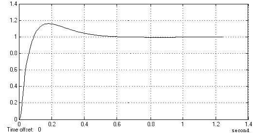
Figure 3. Step response curve of classic controller of photoelectric tracking servo systemFig.3 step response of classic control of opto-electronic tracking servo system
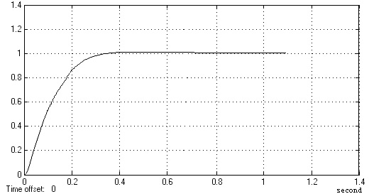
Fig. 4 Step response curve of photoelectric tracking servo system with two-dimensional fuzzy controllerFig.4 step response of opto-electronic tracking servo system with two-dimension fuzzy control
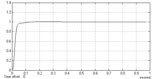
Figure 5 The step response curve of a two-dimensional fuzzy controller photoelectric tracking servo system with a self-adjusting factorFig.5 step response of opto-electronic tracking servo system with self-tuning two-dimension fuzzy control
Comparing the step response curves of the two-dimensional fuzzy controller photoelectric tracking servo system with self-adjusting factor (Figure 5), classic controller and general two-dimensional fuzzy controller (Figure 3 and Figure 4), it can be obtained that self-tuning Factor two-dimensional fuzzy controller and classic controller (its overshoot is larger, higher than 15%, and the adjustment time is greater than 0.4 seconds to achieve ±5%) and general two-dimensional fuzzy controller (its overshoot is 1.2 %, the adjustment time is subject to +-5%, about 0.3 seconds). Compared with the overshoot, its overshoot is smaller, which is 0.6%, and the adjustment time is subject to ±5%, which is 0.04 seconds. The simulation shows that the added proportion The photoelectric tracking servo system with factor self-adjusting two-dimensional fuzzy controller has better dynamic performance.