


I. Overview
A textile machinery factory has used Kinco PLC to form applications on various types of carding machines. In response to the requirements of intelligent and integrated operation of textile machinery, the customer hopes to connect two inverters through PLC, and set and display inverter parameters through text screens. Stepping Technology uses the newly launched dual serial port CPU306EX to transform the original system and successfully realizes the customer's new functions. The frequency converter uses the LENZE SMD series. Here we will not repeat the mechanical process, and focus on the process of communication between Kinco K3 series PLC and Lenze inverter.
Two, CPU306EX dual serial port PLC communication instructions
CPU306EX has two serial communication ports, Port0 physical layer is RS232/485 optional, and integrates three communication protocols: ①MODBUS RTU slave protocol; ②Free communication protocol; ③Communication protocol with EasyProg software. The physical layer of Port1 is RS485, which integrates two communication protocols: ①MODBUS RTU slave station protocol; ②Free communication protocol. In this application, Port0 communicates with the text screen using MODBUS RTU slave station protocol. Port1 communicates with two inverters using free communication protocol.
3. Communication description of Lenze SMD series inverter
The communication protocol of Lenze SMD series inverter is MODBUS RTU slave station protocol. When using MODBUS communication, please pay attention to the following points:
1. The communication line is connected as follows:
A (PLC) → 71 (the first inverter) → 71 (the second inverter)
B (PLC) → 72 (the first inverter) → 72 (the second inverter)
2. Parameter setting (case sensitive):
C01: 8 (MODBUS communication protocol)
C25: 1 (communication parameters 9600, 8, N, 1)
Address of the first inverter:
C09: 2 (station number is 2)
Address of the second inverter:
C09: 3 (station number is 3)
3. Terminal 28 should be shorted with 20.
4. The registers corresponding to low speed, high speed, acceleration time, and deceleration time need to be set as follows:
Set low speed section C37 (4AH)
Set high speed section C38 (4BH)
Set acceleration time C12 (3DH)
Set deceleration time C13 (3EH)
5. Need to read the current frequency register of the inverter as follows:
Reading frequency C50 (50H)
6. When using communication to set new values for the inverter parameters, the inverter must first be unlocked. Just pass parameter 0 to register 49 (31H). (W49=0)
Four, CPU306EX and Lenze SMD series inverter communication instructions
CPU306EX and Lenze inverter adopt free port communication protocol, and the CPU end needs to simulate the MODBUS master station.
The MODBUS data format is as follows:
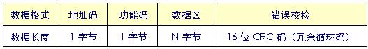
Communication data (information frame) format
Communication information transmission process:
When the communication command is sent from the sending device (CPU) to the receiving device (inverter), the slave that meets the corresponding address code receives the communication command, and reads the information according to the function code and related requirements. If the CRC check is correct, execute the corresponding Task, and then return the execution result (data) to the host. The returned information includes address code, function code, executed data and CRC check code. If there is an error in the CRC check, nothing is returned.
Address code: It is the station number of each inverter, which is unique.
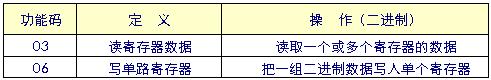
Function code: The function codes that can be defined in MODBUS communication protocol are 1 to 127. Only 03 and 06 are used here.
Data area: The data area includes what kind of information needs to be sent back from the slave or what action to perform.
A 500mS timer is used inside the CPU to control the communication, and the frequency of the inverter is read every 500mS. Read the first frequency converter for the first time, read the second frequency converter for the second time, and then go back and read the first one, and the cycle repeats. When the text screen needs to set data, pause the timer to stop the communication, and return the correct information after the setting is successful. If the setting is unsuccessful, it will return an error message and prompt to reset. If the number of unsuccessful times exceeds 5 times, it will alarm and think that the PLC cannot communicate with the inverter.